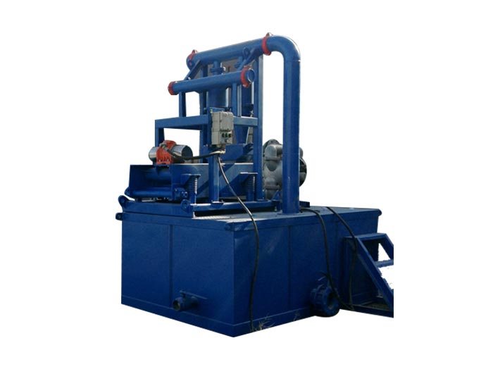
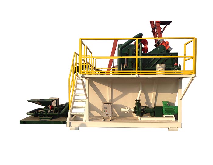
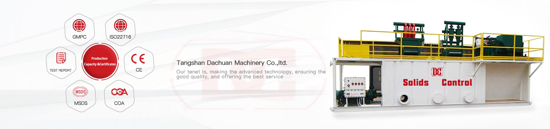
For drilling contractors and equipment procurement teams, choosing a mud cleaner machine requires more than checking nominal treating capacity. The actual performance of a drilling-fluid separation system depends on how the hydrocyclone assembly, linear-motion shaker, feed pipeline, overflow route and supporting pump work together. In an oilfield solids-control process, these components determine whether drilled solids can be efficiently concentrated while useful drilling fluid and weighting material are retained.
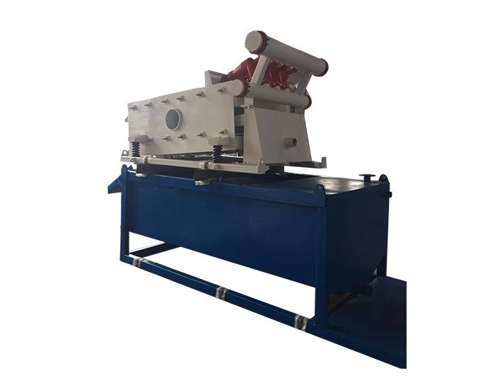
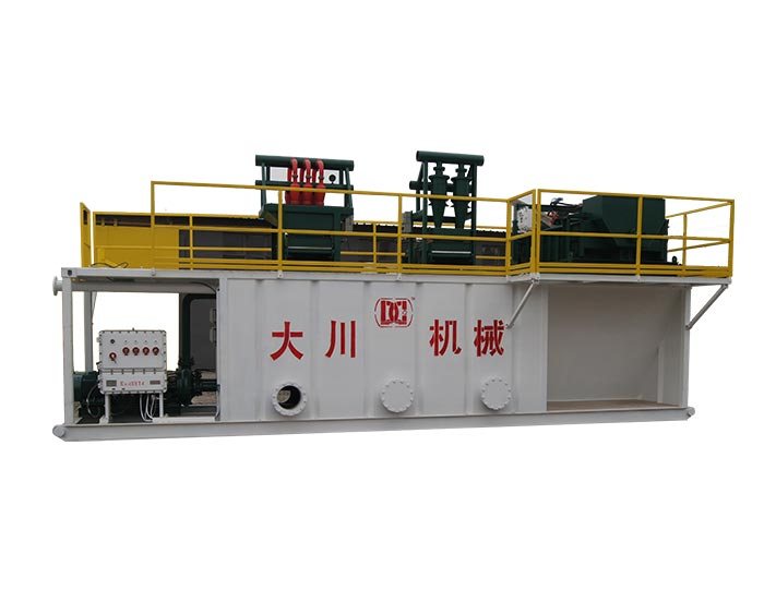
A properly configured drilling mud cleaner normally combines desanding and desilting hydrocyclones with an underflow shaker. The hydrocyclones provide the primary particle separation, while the shaker processes the concentrated underflow and helps recover liquid before solids are discharged. For procurement, the practical questions are therefore focused on cone material, cone diameter and quantity, screen area, feed pressure, pump matching and pipeline arrangement rather than the equipment name alone.
This component-level approach is particularly important when the equipment is integrated into a complete drilling-fluid circulation system. The right configuration should correspond to the expected flow rate, mud properties, separation requirements and operating conditions of the drilling operation.

Wear-Resistant Hydrocyclone Design for Reliable Mud Cleaner Drilling
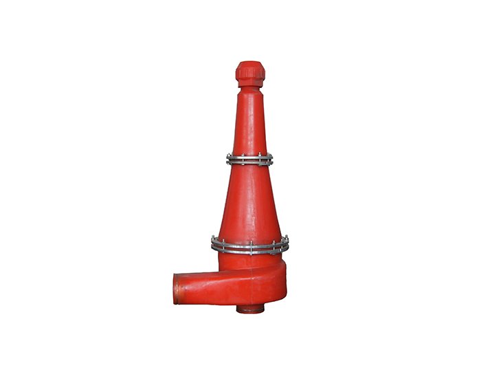
The hydrocyclone assembly is one of the most important components in a mud cleaner drilling system because it performs the high-speed centrifugal separation needed to remove suspended solids from drilling fluid. As drilling mud enters the cyclone under pressure, its rotational flow creates a separation force that causes denser particles to migrate toward the outer wall, while the finer liquid fraction moves toward the central vortex and exits through the overflow.
The construction material of the cyclone directly affects its service life. Drilling fluid can contain abrasive formation cuttings, sand and other solids, so the internal surface is continuously exposed to erosion. Wear-resistant polyurethane is commonly used for hydrocyclone components because it provides a practical combination of abrasion resistance and structural flexibility for continuous drilling-fluid service.
HPolyurethane Material and Erosion Resistance in a Drilling Mud Cleaner
For a drilling mud cleaner, hydrocyclone wear should be considered alongside separation performance. Excessive internal wear can gradually alter the geometry of the cyclone, potentially affecting the flow pattern and separation behavior. A wear-resistant polyurethane construction helps maintain the intended internal profile for longer periods under abrasive operating conditions.
The feed inlet is another important structural area. A smooth and properly arranged inlet helps drilling fluid enter the cyclone with a consistent flow pattern. This matters because hydrocyclone separation relies on controlled rotational movement rather than simple filtration. When the inlet condition, pressure and internal geometry work together, the cyclone can maintain a more predictable separation process.
Desander and Desilter Cones for Better Solids Separation
A mud cleaner machine typically uses different hydrocyclone sizes for different stages of solids removal. Desander cones are designed to handle relatively coarser solids, while desilter cones provide a finer separation stage. Using these two stages together allows the equipment to treat a broader particle-size range without relying on one cyclone size for every separation requirement.
Cone diameter and quantity also affect the total flow capacity. A larger cone can process more fluid per unit, while multiple smaller cones can increase the available separation capacity when arranged correctly. For weighted drilling fluids, this configuration is particularly relevant because the objective is to remove undesirable drilled solids while minimizing unnecessary loss of barite and useful liquid.
Shaker Performance in a Mud Cleaner in Drilling Rig
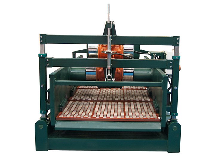
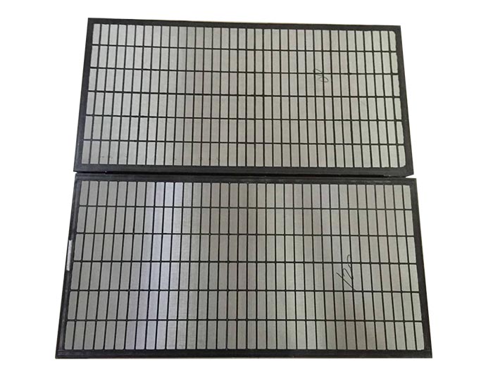
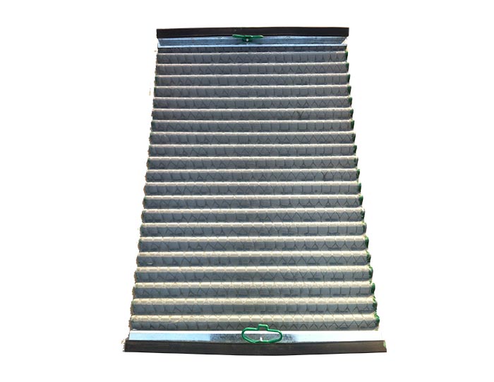
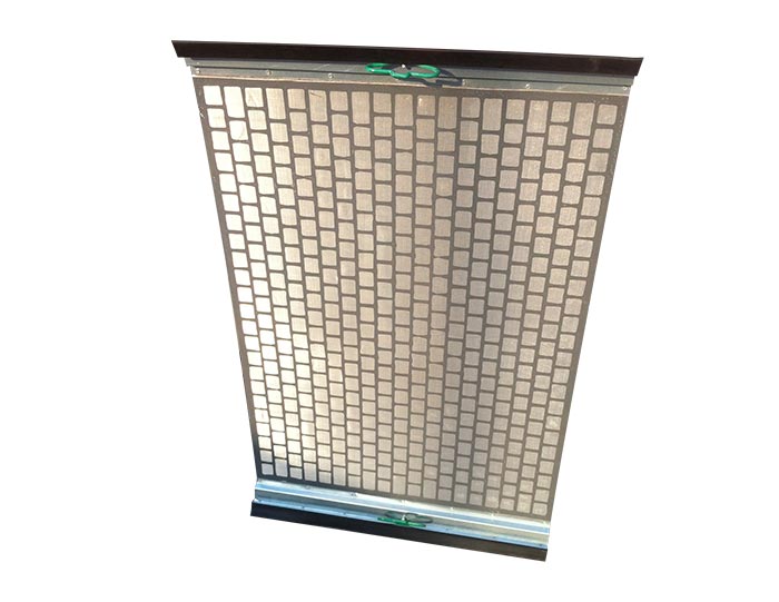
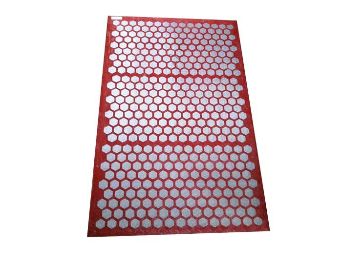
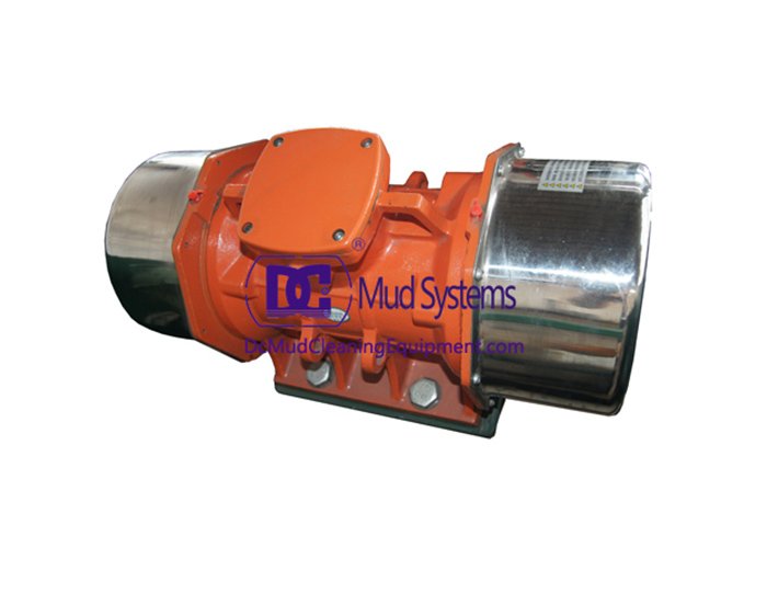
The hydrocyclone underflow is not simply discharged as waste. It can still contain a significant amount of liquid, which is why the shaker section plays an important role in a mud cleaner in drilling rig configuration. After hydrocyclone separation, the concentrated underflow is directed onto the screen surface, where linear motion promotes solids conveyance while allowing recoverable liquid to pass through the screen.
The effectiveness of this stage depends on the relationship between screen area, screen opening, solids loading and underflow volume. A suitable screen provides enough surface area for the concentrated solids to move across the deck without excessive accumulation. The shaker therefore acts as a secondary recovery stage within the mud-cleaning process.
The shaker section also provides a practical advantage in system integration: the hydrocyclones and screening stage are arranged as one treatment unit, allowing concentrated solids to be processed immediately after cyclone separation instead of requiring a separate downstream screening machine.
Feed and Overflow Pipeline Design for Stable Mud Cleaner Machine Operation
Hydrocyclones are pressure-dependent separation devices, so the feed pipeline system is directly connected to the performance of the mud cleaner machine. Stable fluid delivery helps maintain consistent inlet pressure and therefore supports a predictable centrifugal separation process.
The supporting pump should deliver the required flow while maintaining an appropriate pressure range under actual drilling-fluid conditions. Pump selection cannot be based on water flow alone because drilling mud has a higher density and may contain suspended solids. Pipeline resistance, mud density, elevation differences and the number of hydrocyclones operating simultaneously all need to be considered during system design.
Stable Fluid Delivery and Pressure Distribution for Mud Cleaner Drilling
In a mud cleaner drilling system, unstable feed pressure can influence cyclone performance. If pressure fluctuates significantly, the internal velocity and centrifugal force inside the cones can also change. The result may be inconsistent solids separation even when the cyclone itself is correctly designed.
A practical pipeline layout should therefore minimize unnecessary restrictions between the pump and cyclone manifold. The feed route should provide stable delivery to the hydrocyclones, while the manifold should distribute drilling fluid evenly across the active cones. This is especially important when several desander or desilter cones operate simultaneously.
The pump, feed line and cyclone inlet should consequently be treated as one hydraulic system during equipment selection. A correctly sized pump paired with an unsuitable pipeline can still result in poor operating conditions.
Overflow Routing and Turbulence Control in Drilling Mud Cleaner Systems
The overflow line carries the finer liquid fraction away from the hydrocyclone. Its routing should allow the separated fluid to return to the appropriate section of the mud system without creating unnecessary turbulence.
The same principle applies to the underflow connection between the hydrocyclones and shaker. The transfer path should be direct and practical so that concentrated solids can reach the screening surface without unnecessary hydraulic disturbance.
Good pipeline design does not mean simply using larger pipes. The objective is to establish a stable flow path that works with the designed inlet and outlet connections, pump capacity and operating pressure. This becomes increasingly important in drilling-fluid waste management, where unnecessary liquid loss can increase the volume of material requiring subsequent handling.
Supporting Pump and Cone Configuration for a Complete Mud Cleaner Machine
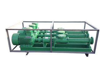
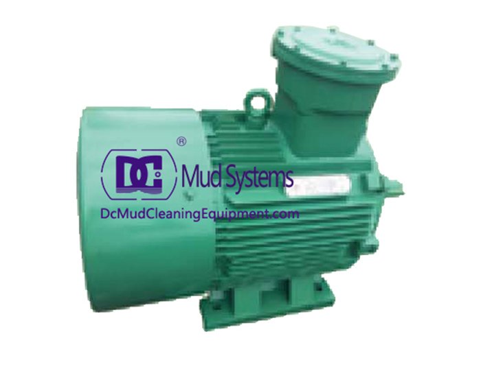
The supporting pressurization pump provides the hydraulic energy required by the hydrocyclone section. Its selection should correspond to both the required treating capacity and the properties of the drilling fluid. Mud density is particularly important because heavier fluid increases the hydraulic load on the pumping system.
Cone configuration should be considered at the same time. Increasing the number of desander or desilter cones changes the available processing capacity, but the pump must also be capable of supplying the required flow and pressure. This is why equipment selection based solely on the number of cones can be misleading.
For projects involving solid control companies, the mud cleaner should be evaluated as one component of the complete solids-control process. It can work alongside shale shakers, centrifugal pumps and other separation equipment, with each machine performing a different stage of solids removal and fluid recovery.
For example, a shale shaker normally handles the initial removal of larger drilled cuttings, while hydrocyclones in the mud cleaner address finer solids. This staged approach allows each separation device to operate within a more appropriate particle-size range.
How to Select a Drilling Mud Cleaner for Different Oilfield Conditions
The selection process should begin with the expected drilling-fluid flow rate rather than with the equipment model. Once the required treating capacity is established, engineers can assess the appropriate combination of desander and desilter cones, shaker area and supporting pump capacity.
Mud density is another key consideration. A system handling weighted drilling fluid may require different hydraulic conditions from one processing lower-density mud. The expected solids loading should also be considered because a high concentration of drilled solids can increase the load on both the hydrocyclones and the underflow shaker.
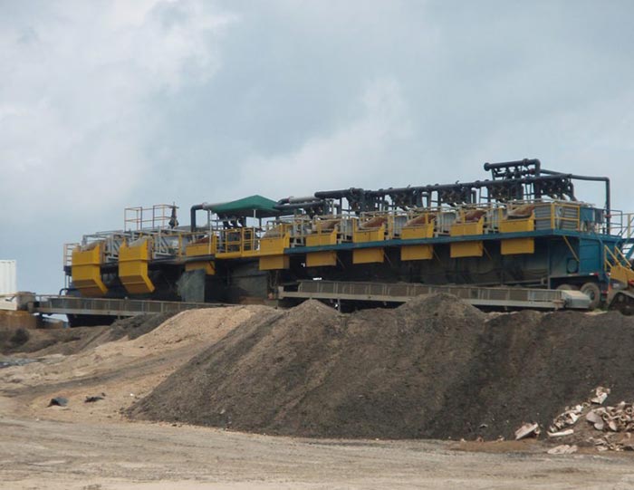
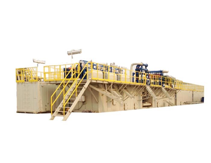
Installation space is a further practical factor. An integrated drilling mud cleaner can combine multiple separation functions within one equipment package, which can simplify the arrangement of a solids-control system where available deck or site space is limited.
For offshore applications, equipment selection should additionally consider the overall arrangement of the drilling-fluid system, accessibility for screen replacement, maintenance requirements and the relationship between the mud cleaner and other solids-control units. These considerations are particularly relevant to a solid control offshore drilling company planning equipment around restricted installation space and continuous operation.
FAQ About Mud Cleaner Machine Components
What are the main components of a mud cleaner?
The main components generally include desander hydrocyclones, desilter hydrocyclones, an underflow linear-motion shaker, feed and overflow pipelines, and a supporting pressurization pump.
Why are both desander and desilter cones used?
They address different particle-size ranges. Desander cones handle relatively coarser solids, while desilter cones provide finer separation. Combining them allows the drilling fluid to undergo staged solids removal.
What does the underflow shaker do?
The shaker processes the concentrated hydrocyclone underflow. Its screen separates recoverable liquid from the concentrated solids and helps reduce unnecessary drilling-fluid loss with the discharged solids.
Why is pump selection important?
Hydrocyclones require suitable feed pressure and flow to establish their internal centrifugal separation pattern. Pump capacity therefore needs to match mud density, system resistance, required flow and the selected cyclone configuration.

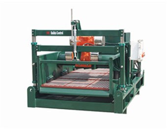 Linear Motion Shale Shaker In Drilling Rig
 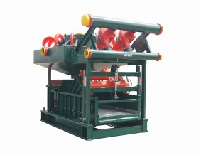 Oilfield Mud Cleaner
 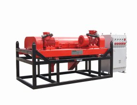 Drilling Fluid Decanter Centrifuge
 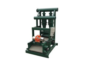 Drilling Mud Desander
 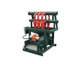 Hydrocyclone Desilter
 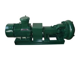 Centrifugal Pump/Centrifugal Mud Pump
 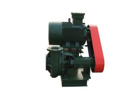 Shear Pump
 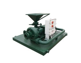 Jet Mud Mixer
 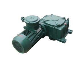 Horizontal Mud Agitator
 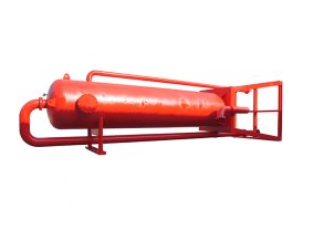 Constant Pressure Drilling Fluid Mud Gas Separator
 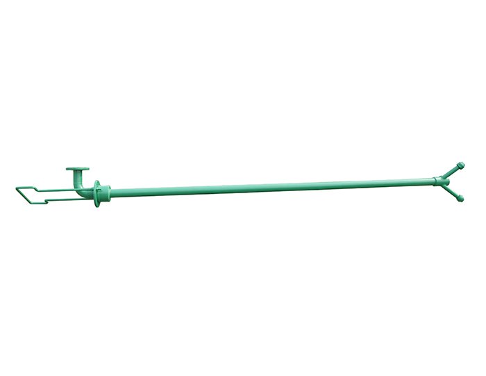 Mud Gun
  Mud Tank
 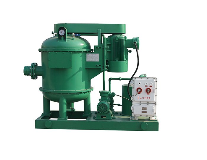 Solids Control System Vacuum Degasser
 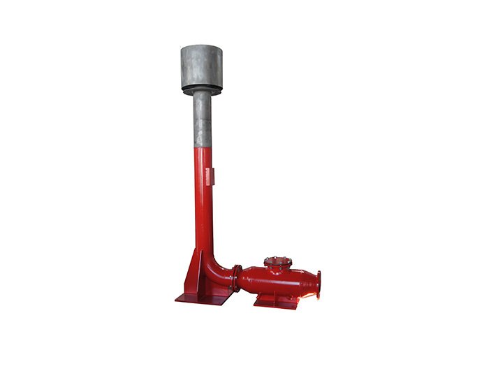 Flare Ignition Device
 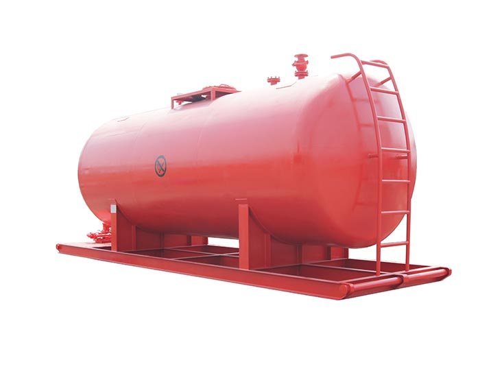 Diesel Tank
 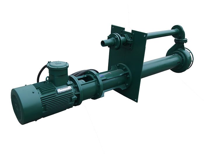 Submersible Slurry Pump